Hello,
your vehicle models in Common Road have been very useful. However, I tried to upgrade the open source F110 gym simulator with your multibody model, and I noticed some weird behavior. The evolution of the states seems to be correct; however, I do not think that the forces inside the model are correct. When you run the example (from Common Road vehicle models, I am using python code), from the graph of the position, you can see that the car is steering to the left, so I would expect that the majority of the force F_z will be transferred to the right side of the vehicle (F_z_LF < F_z_RF and F_z_LR < F_z_RR). But this is not true. In fact, the exact opposite is happening. The same thing happens when the car steers to the right; the majority of the force is on the right two wheels, which I do not think is correct. Maybe just the naming is not correct, and the right front wheel is, in fact, the left front wheel, etc.? I tried to look into it, but I have not been successful yet. Can someone please help me look into this?
Thank you for the answer.
Tomas Nagy
Hi Tomas,
thanks for your question. I will look into the equations of the MB model and double-check them again.
Just as a side-note: We have recently updated the vehicle models on PyPi (see here). I just noticed that the repository is not updated yet, I will take care of this today. However, in the updated version we have not changed the MB model, so this probably won’t solve the issue you mentioned.
Best,
Gerald
Hi Gerald,
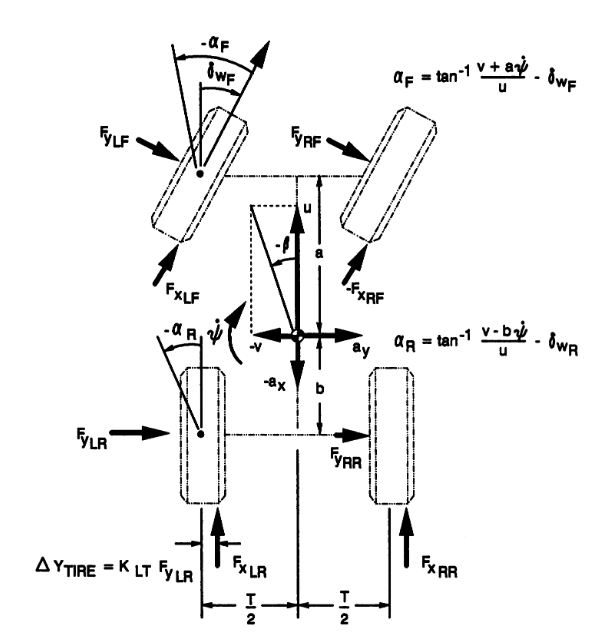
today I have already looked into the equation. I compared code with common road equations and also with the original document (Vehicle dynamic stability and rollover [1992]). I did not find any mistakes there. However, I might find a mistake in the kinematics of the MB model. When we compare reference frames between common road kinematics and the original document, in the common road, the yaw angle and Beta angles are defined to be positive in the counterclockwise direction; however, in the original document, they are defined to be positive in the clockwise direction (attached figure).
When I change the original equation of the kinematics from
math.cos(beta + x[4])*vel
math.sin(beta + x[4])*vel
to
math.cos(-beta - x[4])*vel
math.sin(-beta - x[4])*vel
it seems to behave as expected (the only thing this change is basically that the positive steering angle now moves the car to the right instead of left). I am not 100% sure that this is the correct solution, I will look into this more tomorrow.
Thanks for your quick answer,
Tomas Nagy
Small correction.
This is definitely not correct
math.cos(-beta - x[4])*vel
math.sin(-beta - x[4])*vel
because the initial condition would be wrong. We need to change just the integration of the yaw so
f.append(x[5]) → f.append(-x[5]).
So I think that the equations should be like this
math.cos(-beta + x[4])*vel
math.sin(-beta + x[4])*vel
...
f.append(-x[5]).